Quick answer
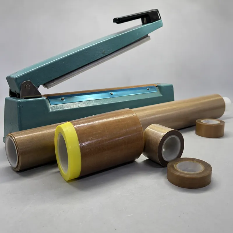
Choose non-adhesive PTFE-coated fiberglass fabric where the machine holds a release cover mechanically, and adhesive-backed tape where the specified mounting surface requires a bonded strip. Record backing thickness separately from adhesive thickness and match any adhesive-free zone to the machine drawing. Diagnose sticking and seal defects against the complete heat, pressure and cooling cycle before changing the material or settings.
01 / Heat sealer material selection
Identify the part being replaced
The PTFE surface separates hot equipment from the film passing through a heat sealer. The woven fiberglass supports that surface and helps the strip hold its dimensions. Adhesive, where present, attaches the backing to the specified machine surface. These are separate functions, and each belongs in the replacement specification.
A brown strip over a heater, tape fixed to a jaw and an endless band moving with the package are different components. Before ordering, identify which face touches the package, how the part is retained and whether it moves. Keep a photograph and the machine part reference with the drawing.
| Format | How it works | What to specify |
|---|---|---|
| Non-adhesive coated fabric | A release cover held by the machine’s clamps, tensioning or other mechanical retention. | Coated-fabric grade, finished thickness, width, length and attachment details. |
| Adhesive-backed glass cloth tape | A coated-fabric release face with pressure-sensitive adhesive on its mounting side. | Backing and adhesive thickness, adhesive system, coverage and mounting surface. |
| Zone tape | Adhesive is placed in selected bands, leaving a defined area without adhesive. | Overall width, clear-zone width, adhesive-band widths and position relative to the heater. |
| PTFE film tape | A film backing instead of a woven-glass backing. | The exact film construction and attachment; match it to the machine specification rather than substituting by colour. |
| Moving sealer belt | A fabricated loop travels around rollers through the sealing process. | Finished circumference, width, thickness, joint and machine fit. |
02 / Heat sealer material selection
Read the sealing cycle before comparing tapes
An impulse sealer heats during a controlled part of its cycle. On machines with a defined cooling stage, the jaws remain closed while the seal sets. A constant-temperature hot bar stays heated, and the film receives heat during contact. Continuous machines add motion through the heating and cooling sections. Record the actual equipment type before comparing replacement materials.
The cover lies in the heat path and the contact stack. Its thickness, flatness and surface condition affect the contact presented to the film. Pressure distribution, film tension, jaw alignment and cooling also affect the finished seal. A release surface that prevents sticking cannot, on its own, establish seal strength or package integrity.
Record the film construction and thickness, seal width, heating control, dwell, pressure or closure arrangement, cooling stage and production rate. An impulse timer setting is not a measured film temperature. A hot-bar setpoint is the controller’s reference, not a direct reading at every point of the film interface.
03 / Heat sealer material selection
Separate backing thickness from installed tape thickness
A catalogue thickness can describe the PTFE-coated fabric alone or the complete tape without its removable liner. Ask which definition applies. The backing measurement already includes the glass weave and PTFE coating; adhesive thickness is a separate addition. The release liner is removed during fitting and does not belong in the installed thickness.
For example, a 0.13 mm coated backing with 0.04 mm adhesive gives a nominal 0.17 mm installed tape. A tape described as 0.13 mm total is a different thickness statement. This is an accounting example, not a SIFMAT stock specification. State the measurement method and tolerance when comparing actual samples.
CROSS-SECTION / FULL ADHESIVE
Film contacts the release face ↓
Installed tape thickness = A + B
The removable release liner is excluded.
ADHESIVE-SIDE VIEW / ZONE LAYOUT
One example of selective adhesive placement
band
in this zone
band
Overall width includes all three zones
Specify each band and its position on the drawing.
| Measurement | Include | Exclude or identify separately |
|---|---|---|
| Coated backing thickness | The finished PTFE-coated fiberglass backing. | Pressure-sensitive adhesive and removable liner. |
| Installed tape thickness | Backing plus adhesive in a fully coated area. | The removable liner; identify a different thickness in any adhesive-free zone. |
| Strip width and length | Finished cut dimensions and tolerances. | Do not substitute roll-core size or nominal sealing length. |
| Thickness units | Millimetres or mils, written explicitly. | One mil is 0.001 inch, or 0.0254 mm; it does not mean one millimetre. |
04 / Heat sealer material selection
Choose thickness and surface together
A thicker backing changes the path between the heater and the film. With otherwise comparable materials, increasing thickness increases the resistance to heat flow through that layer. It also changes the installed profile. The sealing response depends on the whole assembly, including adhesive, contact quality and the machine’s heating cycle.
A thinner strip reduces the layer thickness, but it must still suit handling, contact pressure and repeated use. Choosing the thinnest option without checking wear and coating condition simply moves the problem to another part of the cycle. Start from the machine’s specified construction and evaluate a change with a controlled sample comparison.
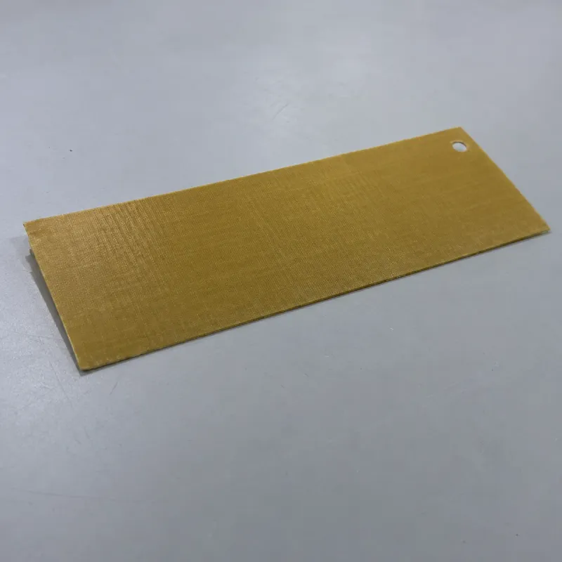
Compare the working face as well as the thickness. A visible weave, a smoother coated surface and a worn face present different contact conditions. Check the acceptable seal appearance, imprint and release with the actual film. Equal overall thickness does not establish equal coating coverage, texture or service life.
05 / Heat sealer material selection
Specify the adhesive system and its exact location
The adhesive must hold the backing on the intended mounting surface through the operating and cleaning cycle. Record the surface material, finish, normal and peak exposure, repeated heating, contact pressure and removal requirements. Identify the supplied adhesive system and its finished-tape operating limits.
Silicone pressure-sensitive adhesive is used in PTFE glass cloth tapes for heated equipment. Acrylic and other systems also exist for particular requirements. These are material categories, not interchangeable temperature ratings. Choose the identified tape grade rather than applying a base fabric’s heat rating to every adhesive-backed version.
A zone tape leaves an adhesive-free working area while adhesive bands attach the strip elsewhere. Specify both band widths, the clear zone and their registration to the machine reference edge. This is a machine-specific layout: neither adding adhesive under the heater nor removing adhesive from an existing design is a general upgrade.
- State whether adhesive covers the full width, one band, two bands or another defined pattern.
- Identify the adhesive face and the reference edge on the drawing.
- Keep adhesives and bonding edges out of process-contact areas where the machine specification requires a clear zone.
- Confirm nonstandard adhesive systems and zone layouts as a separate construction review.
06 / Heat sealer material selection
Restore a flat, correctly located contact surface
Carry out replacement with the equipment isolated and cooled under its maintenance procedure. Record the original layer order before removing the worn part. A release cover, heater support and electrical insulation perform different jobs; replace the specified component without redesigning the assembly.
Check the mounting area for residue, damage and raised edges. Use the approved cleaning method and allow the surface to reach the required clean, dry condition before fitting. A new strip applied over residue or overlapping remnants starts with an uneven contact profile.
Fit the specified part without folds, trapped debris or unintended overlaps in the seal path. Match holes, clear zones and retained ends to the drawing. Do not stretch a glass-reinforced strip to correct a dimensional mismatch, and do not add extra tape layers as an unreviewed repair.
07 / Heat sealer material selection
Diagnose the pattern before changing the settings
Record where the fault occurs along the jaw, when it first appears and whether it changes as the machine warms up. Keep a failed package beside an acceptable one and mark their positions relative to the jaw. Inspect the corresponding cover, heater area and pressure face under the equipment maintenance procedure.
A weak seal, a sticking film and a lifting tape edge are different observations. Each needs its own checks. Changing heat, time, pressure and material together hides which change affected the result and makes the next replacement harder to specify.
| Observation | Inspect on the material or machine | Check in the process |
|---|---|---|
| Film sticks when the jaws open | Residue, damaged release face and local loss of coating. | Film identity, heating input, contact time and the specified cooling or release stage. |
| Wrinkles repeat at one jaw position | A fold, overlap, trapped residue or uneven contact at that location. | Film presentation, tension and jaw alignment. |
| Adhesive-backed tape lifts at an edge | Mounting-surface condition, adhesive layout, fit and evidence of movement. | Actual heat exposure, cleaning compatibility and the identified adhesive grade. |
| A small area wears through repeatedly | A raised point, damaged heater area, sharp contact or pressure-face defect. | Closure and loading at the same position over repeated cycles. |
| The seal looks uneven or remains weak | Contact flatness, cover condition and pressure-face condition. | Film construction, contamination, heat, dwell and cooling against the approved process. |
| The first packages differ from later ones | Condition and fit of the cover before and after warm-up. | Warm-up sequence, production rate and the equipment’s control behaviour. |
08 / Heat sealer material selection
Separate removable residue from a damaged release face
Clean using a method approved for the complete construction. Compatibility with PTFE alone does not establish compatibility with the adhesive, cut edges or adjacent machine parts. Use a soft, non-abrasive cleaning tool and inspect the same area after the surface is clean and dry.
Residue sits on the working face; worn coating, exposed yarns, cuts and permanent creases are damage to the material. Cleaning does not replace missing coating or restore broken reinforcement. Remove damaged covers from service and examine the matching machine location before fitting another strip.
Record service by the actual duty: cycles, film, settings, cleaning and the location of wear. A fixed replacement interval cannot be transferred between a lightly used bench sealer and a continuously operated packaging line. Set the inspection and replacement plan from the machine requirements and documented service condition.
09 / Heat sealer material selection
Approve the material and the finished seal separately
Give each candidate a sample identifier and keep its backing, adhesive and cut drawing with the trial record. Establish fit and contact flatness first. Then run the specified film and loading pattern under the machine’s approved setup procedure. Record any process adjustments and the reason for each one.
Compare the first packages, the warmed-up machine and repeated production cycles. Assess release, visible marking and residue alongside the package’s required seal tests. Define the relevant seal-strength or leak acceptance method before the trial. Easy release and a neat-looking line do not establish package integrity.
| Stage | Record | Accept against |
|---|---|---|
| Incoming material | Sample ID, backing and total thickness, dimensions, surface and adhesive layout. | The agreed material specification and drawing. |
| Fitted condition | Layer order, location, flatness, retained ends and clear zones. | The machine’s component and installation requirements. |
| Sealing cycle | Film, heating control, dwell, closure or pressure, cooling and production rate. | The established production process and permitted adjustments. |
| Finished package | Release, wrinkles, contact marks and the specified seal test results. | The package quality requirements, not appearance alone. |
| Repeated operation | Cycles, residue, edge lifting, local wear and condition after cleaning. | The inspection plan and intended service duty. |
10 / Heat sealer material selection
Order from a complete replacement specification
SIFMAT supplies PTFE-coated fiberglass fabric, adhesive-backed tape and machine-specific converted formats. Send the existing part reference, a dimensioned drawing and photographs of both faces. Identify the working face, mounting method and problem the replacement needs to resolve.
For a cut strip, include overall width and length, hole diameters and positions, corner details, backing thickness and tolerance. For a tape roll, add roll length and adhesive coverage. Where a zone layout is required, dimension every band from a defined reference edge.
- Equipment: machine model, part location, impulse or constant-temperature operation, and the existing part reference.
- Film: construction, thickness, seal width and relevant product-contact conditions.
- Material: coated-fabric backing, surface finish, installed thickness, adhesive identity and layout.
- Duty: heating and cooling conditions, cycle rate, pressure or closure, cleaning and observed failure pattern.
- Order: quantity per specification, sample-approval requirements and required delivery date.
Buyer questions
PTFE heat sealer fabric and tape questions
Should I use PTFE cloth or adhesive-backed tape on a heat sealer?
Use the format specified by the machine’s attachment design. Non-adhesive coated cloth suits a mechanically retained release cover; adhesive-backed tape attaches to a defined mounting surface. A moving sealing band is a separate fabricated component. Match the fitted part before choosing thickness or adhesive.
What thickness of PTFE tape should I use?
Start with the specified replacement construction. State whether the value covers the coated backing alone or the backing plus adhesive, excluding the removable liner. Evaluate a thickness change against fit, thermal response, release and the finished seal using the actual machine and film.
Does a thicker PTFE tape last longer?
Thickness alone does not determine life. The glass backing, coating coverage, contact profile, adhesive, heat exposure and cleaning also matter. A thicker tape changes the installed stack and heat path, so compare the complete construction under the intended sealing cycle.
Can I use the PTFE fabric temperature rating for the finished tape?
Use the finished tape’s specified limit. The adhesive and its mounting conditions form part of that construction. Confirm normal and peak exposure, duration and repeated cycling rather than assigning an unbacked fabric’s rating to every adhesive-backed tape.
When is an adhesive-free centre zone needed?
Use a clear zone where the equipment specifies a working area without adhesive and attachment bands elsewhere. Dimension the clear width and band positions against the heater and mounting surfaces. A zone tape is a defined layout, not a universal replacement for full-width adhesive tape.
Why does film stick after I replace the PTFE cover?
Check the installed surface for residue, folds, wrong orientation or coating damage, then compare the heating, dwell and cooling stages with the approved process. Confirm the film and fitted material identities. Raising the heat before these checks can obscure the cause and damage the replacement.
Can a new PTFE tape fix a weak or leaking seal?
Replacing a worn or incorrectly fitted cover addresses that component. Seal performance also depends on the film, contamination, jaw contact and the heating, pressure and cooling cycle. Verify the finished package with its specified acceptance tests after replacement.
Your next step
Specify Your Heat Sealer Fabric or Tape
Send the machine reference, fitted-part photographs, dimensions and sealing conditions. Include the backing and total thickness, adhesive layout, film details and the fault you need to resolve.
Specify Your Heat Sealer Fabric or Tape