Quick answer
Choose the splice around the job at the joint: product contact, passage over the smallest pulley, airflow through an open belt and access for installation. Shortlist a bonded fabric splice where a controlled contact profile matters, and a detachable connection where the belt must be joined on the machine. Specify the belt, joint, reinforcement and running conditions together.
01 / PTFE belt joint selection
Start at the most demanding point on the machine
The splice returns to every roller, support and process station once per belt revolution. A connection that fits between the machine frames can still catch a scraper, mark a laminate or interrupt airflow. Start with the point that gives the joint the least clearance or the most demanding contact.
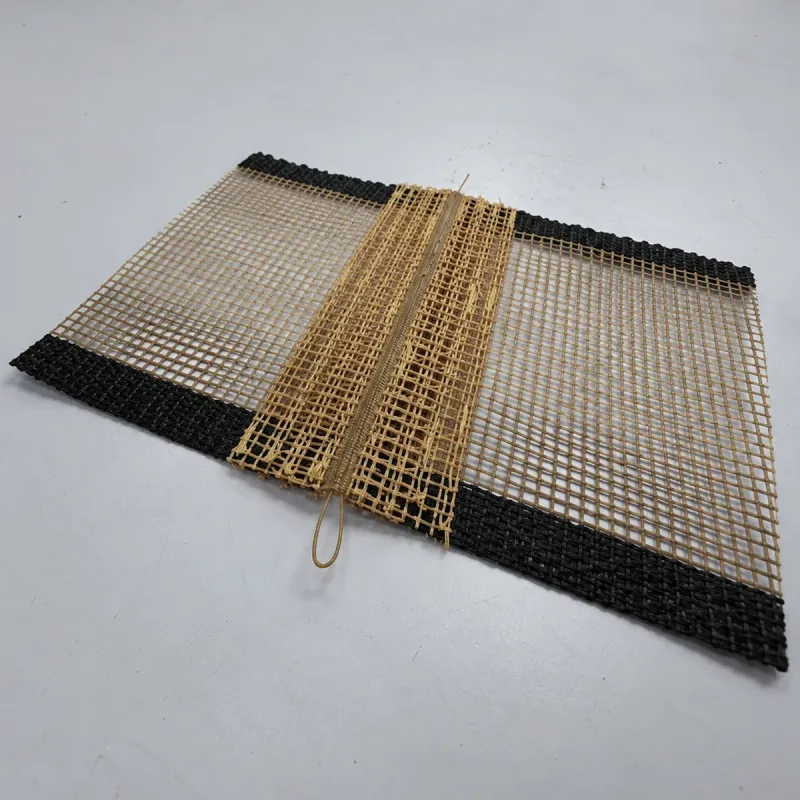
Identify the construction first. Closed PTFE-coated fiberglass fabric provides a continuous release face; open mesh leaves passages between coated strands. A moving belt also needs a load-bearing connection, edge reinforcement and a tracking arrangement. A cut tray liner does not have the same specification.
| Question | What to record | Effect on selection |
|---|---|---|
| What touches the seam? | Product, heated platen, nip, scraper, guide or support surface. | Determines the acceptable step, exposed hardware and surface finish. |
| Where does it bend? | Smallest pulley diameter, reverse bends and support transitions. | Sets the geometry to check with the complete joint, including its underside. |
| Must air pass through it? | Airflow direction, loaded coverage and the area covered by the seam. | Makes local opening loss and reinforcement coverage relevant. |
| How will it be installed? | Access to both belt ends, pin insertion space and ability to fit a closed loop. | Separates factory-closed belts from connections made on the machine. |
02 / PTFE belt joint selection
Compare the joint construction, not just its name
“Finger,” “overlap” and “spiral” describe different features of a connection. Record the cut pattern, connection material, reinforcement, finished thickness and installation method. Two joints with the same name can have different contact profiles and bending behavior.
An endless belt is a closed loop. It can have a bonded splice or a detachable connection; “endless” does not mean “seamless.” State whether the belt must arrive closed or be supplied open for installation.
| Joint family | Construction | Selection priority | Detail to check |
|---|---|---|---|
| Overlap | One belt end lies over the other and is bonded across the overlap. | A bonded connection where the available profile suits the machine. | Added thickness, lap direction, contact edge and bending through the overlap. |
| Scarfed overlap | End thickness is reduced to form a more gradual bonded transition. | A lower step on a closed-fabric contact surface. | Remaining reinforcement, transition length and finished thickness across the seam. |
| Reinforced butt | Ends meet edge to edge; a bonded strip supports the connection. | A top face without a full-thickness overlap. | Thickness and stiffness of the underside strip, plus clearance on the return path. |
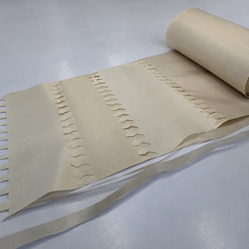
| Finger or notched bonded splice | Complementary cuts distribute the seam along the belt length, with the specified connection layers. | A distributed seam layout for repeated running and contact-sensitive work. | Cut shape, finger roots, bond coverage, reinforcement and final profile. |
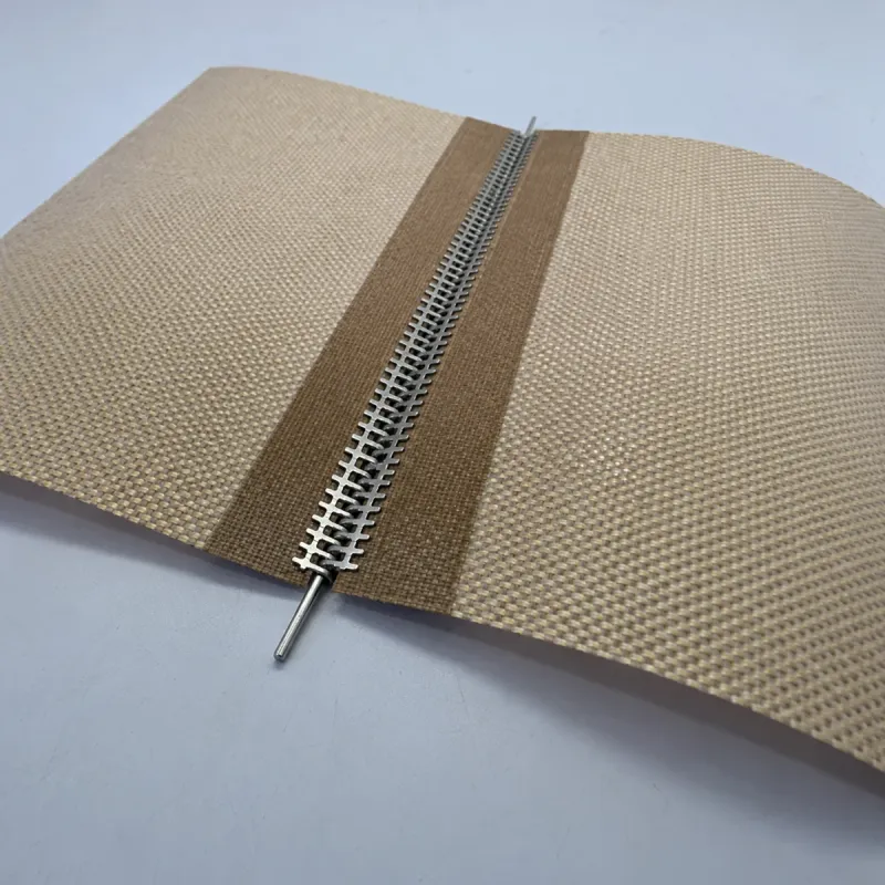
| Loop or spiral connection | Prepared belt ends connect through loops or lacing and a joining pin. | A detachable connection, particularly when installing an open belt. | Connector and pin material, local openings, edge reinforcement and access to the pin. |
| Metallic fastener | Fasteners attach to prepared ends and connect across the belt width. | An accessible mechanical connection for belt fitting and removal. | Projection, attachment, pin retention and permitted metal contact. |
03 / PTFE belt joint selection
Why a finger splice spreads the seam along the belt
A straight butt cut interrupts the fabric at one transverse position. A finger cut places that boundary at different positions along the belt length. The matching ends align into a distributed seam instead of one straight line across the full width.
The fingers do not hold the belt together as a mechanical lock. Cutting interrupts load-bearing fiberglass yarns. The bonded connection and any reinforcing layers transfer force between the prepared ends. Finger length, root shape and layer arrangement form part of that connection design.
During running, the joint repeatedly bends around rollers. Assess the entire bonded region, including reinforcing strips and transitions. A finger outline alone does not establish splice strength, flexibility or a flush surface. Longer fingers also require more accurately controlled preparation and alignment.
A straight seam
The fabric ends meet at one position across the width.
A distributed finger seam
The cut boundary changes position along the length.
How a reinforced bonded joint transfers force
The connection layers transfer load between the prepared ends. Finger shape alone is not a mechanical lock.
04 / PTFE belt joint selection
A detachable connection changes the contact surface
Loops, spiral lacing and metallic fasteners allow the ends to be connected on the machine. Check the complete assembly: the pin, lacing or clips, the end reinforcement and the belt edges. The belt must be accessible where the connection is assembled and where the pin is inserted or removed.
Non-metallic lacing is a construction choice, not a temperature or electrical rating. Identify the connector and pin materials separately. For metallic connections, record exposed edges and contact with the conveyed product, scraper or heated surface. A covered fastener changes the profile and must be assessed as part of the joint.
Edge reinforcement also supports the end connection. Make sure the seam closes across the intended width without forcing the reinforced edges out of alignment. A correctly joined center section does not compensate for a distorted edge or protruding pin.
05 / PTFE belt joint selection
Measure joint thickness on both sides of the belt
Nominal belt thickness describes the base construction. Measure the finished joint as well: the maximum thickness, the step above the working face and the projection beneath it. A flush top can still have a reinforcing strip underneath that contacts the return support.
Compare the profile with the smallest clearance under the relevant running conditions. Include nips, doctor blades, fixed supports, guide channels and reverse bends. Record which side contacts each roller. A joint that bends around a large drive pulley may behave differently at a smaller return roller.
Thickness and bending stiffness are separate fields. Two joints of similar thickness can have different reinforcing materials, bonded lengths and transitions. Use the selected assembly’s pulley requirements and verify it on the actual belt path; do not size rollers from the PTFE coating name.
| Measurement | Where to check | What it tells you |
|---|---|---|
| Working-face step | Leading and trailing seam edges, including any cover. | Potential contact with the product, scraper or process nip. |
| Maximum joint thickness | Across the belt width and through the full seam region. | Space occupied by the complete connection. |
| Underside projection | Bonding strip, reinforcement and fastener attachment. | Clearance on pulleys, supports and the return path. |
| Bend transition | Both ends of the reinforced region and each finger root. | Locations to watch for lifting or concentrated flexing during the trial. |
06 / PTFE belt joint selection
Treat the mesh seam as a local change in open area
The open area of the parent mesh does not describe the finished seam. A bonding film, reinforcing strip or doubled mesh layer changes the passage through that region. Spiral and loop connections introduce their own pattern of openings and contact points.
On a through-air drying line, inspect the seam against the loaded belt and the supporting conveyor. Record its width in the travel direction, the openings that remain and residue buildup after use. Keep the airflow and loading conditions consistent when comparing two constructions.
A fixed station sees the joint once per belt revolution. The interval is running belt circumference divided by belt speed. For example, a 4 m circumference at 8 m/min gives a joint passage every 30 seconds. This is a timing example for locating a recurring event, not a drying result or a product specification.
07 / PTFE belt joint selection
Match the splice to the process at the contact point
Record actual exposure at the joint: heated-air temperature, hot-surface contact, dwell, pressure and cleaning conditions. A base-fabric temperature range does not rate a splice containing a separate bonding film, connector, pin or cover.
For food-contact or electrical requirements, specify the finished connection materials as well as the belt body. A polymer name, black color or metallic fastener description does not establish approval for the application.
| Process | Primary concern at the seam | Sample check |
|---|---|---|
| Screen-print drying and curing | Mesh support, local airflow, conveyed-item stability and passage through the dryer. | Observe product handling at the seam and record the joint through the actual running cycle. |
| Garment fusing and lamination | Contact profile, release, pressure and surface imprint. | Run the actual fabric and adhesive system; inspect the area that crosses the seam after cooling. |
| Continuous heat sealing | Thickness transition through the sealing station and stable belt motion. | Inspect the seal where the joint passes; verify seal quality with the packaging process’s acceptance method. |
| Food-processing conveyors | Product release, accessible cleaning and connection-material suitability. | Inspect residue around the joint, exposed hardware and reinforced edges after the specified cleaning cycle. |
08 / PTFE belt joint selection
Specify finished circumference and installation access
State finished belt width and endless circumference as separate dimensions. For an open belt, distinguish the supplied length from the circumference required after joining. The fabrication drawing must account for the chosen overlap, preparation and connector geometry; do not add a guessed joint allowance to the required running circumference.
Use the machine drawing and its take-up range when replacing a worn belt. The removed belt can help identify the joint and hardware, but wear, distortion and the measurement condition affect its dimensions. Record how the old belt was measured and whether the machine was at its normal operating adjustment.
Show the travel direction, product-contact side, edge reinforcement, guides, holes and pin position. Check installation space before ordering a closed loop. For a detachable connection, include the clearance needed to insert and retain the pin. For on-machine bonding, the access must suit the specified preparation and pressing equipment.
- Put the joint location and geometry on the fabrication drawing, with dimensioned end and underside views.
- Define the overall width and usable working width when edge reinforcement or guides occupy part of the belt.
- List the smallest pulley, reverse bends, support layout, speed, loading and tension arrangement.
- Identify every connector, pin, cover and reinforcing material in the approved assembly.
09 / PTFE belt joint selection
Approve the splice with a controlled running trial
Agree the acceptance criteria before the trial. Keep the sample identifier with the belt grade, joint drawing and machine settings. Inspect a representative assembled joint; a material swatch cannot establish connection behavior.
Check fit and clearance before processing product. Then assess the joint in the specified production cycle and after the agreed cleaning sequence. Follow the machine’s setup and maintenance procedure for tension and tracking. Compare the same positions and conditions when evaluating another construction.
| Stage | Observation to record | Acceptance field to agree |
|---|---|---|
| Incoming inspection | Width, circumference, seam alignment, top/underside profile, pin retention and edges. | Drawing tolerances, profile limits and workmanship criteria. |
| Initial running | Passage over the smallest pulley, reverse bends, supports and guides. | Clearance, connection stability and permitted contact. |
| Process exposure | Release, marking, lifting, residue and the result where the splice passes the station. | Product finish and the process-specific quality requirement. |
| After cleaning | Residue around the joint, coating condition, exposed yarns and attachment changes. | Cleanability and condition required before return to service. |
| Repeated use | Change in the same inspection points over the agreed evaluation period. | Inspection interval, replacement criteria and trial scope. |
10 / PTFE belt joint selection
Use the wear location to investigate a recurring fault
Inspect where the change starts. Leading-edge lift calls for a review of the lap direction, contact surfaces and bond condition. Underside rubbing points to the support path or clearance. Damage at one reinforced edge needs a check of alignment, guiding contact and connector attachment.
Treat these observations as a way to organize the investigation. The same symptom can have more than one cause. Record when it appears, its location across the belt and its relation to joint passage, loading and cleaning. Replacing the belt with a thicker grade leaves a machine-clearance problem unresolved.
Take a damaged connection out of production for assessment when it no longer meets the agreed condition. Preserve the sample reference and photographs of the top, underside and both edges so the replacement specification addresses the observed fault.
Buyer questions
PTFE belt joint questions
Which PTFE conveyor belt splice is best?
Choose the splice that meets the contact profile, pulley geometry, airflow and installation requirements of the machine. A low-profile bonded joint and an accessible detachable connection solve different problems. Specify the finished assembly before comparing options.
Is a finger splice stronger than an overlap splice?
The outline alone does not establish strength. Finger cuts distribute the seam along the belt length, while the connection layers and reinforcement carry force between the cut ends. Compare tested assemblies with the same load, exposure and bending conditions.
Does an endless PTFE belt have no seam?
Endless describes a closed loop. The loop can contain a bonded splice or a detachable connection. If a process requires a particular seam profile or a truly seamless construction, state that requirement separately.
Can a mesh belt splice block airflow?
Yes. Bonding films, reinforcing strips and overlapped layers change the openings locally. Inspect the assembled seam rather than applying the parent mesh’s open-area figure to the whole belt.
Does the PTFE fabric temperature range also rate the joint?
No. The splice includes its own bonding, reinforcing or fastening materials. Approve the complete belt for the actual temperature, exposure time, pressure, movement and cleaning cycle.
Can SIFMAT quote a replacement belt from the old belt alone?
Send the old belt’s reference and photographs together with the machine dimensions and operating conditions. State how the old belt was measured and identify its joint, edges and guides. The machine drawing and required finished circumference resolve dimensions affected by wear or adjustment.
Your next step
Specify Your PTFE Belt Joint
Send the machine reference, belt width and circumference, current-joint photographs and operating cycle. Include the smallest pulley, edge details and installation access so the belt and connection can be reviewed as one assembly.
Specify Your PTFE Belt Joint