Quick answer
Choose a PTFE fusing machine belt around the fabric and interlining, the permitted surface impression, the complete splice profile and the machine’s tracking system. Specify the upper and lower belts separately. Then approve fit, release and bond quality under the same measured fusing conditions. Belt colour or nominal thickness alone cannot establish suitability.
01 / Fusing machine belt selection
The belt is part of the fusing process
A collar panel that releases cleanly can still show a weave impression. An interlining that bonds at the centre can still lift near an edge. A replacement belt has to carry the assembly, present a suitable contact surface and pass through the machine without disturbing the established heat, pressure and cooling cycle.
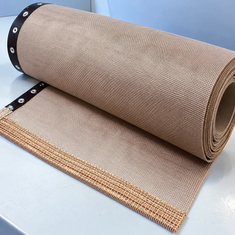
PTFE-coated fiberglass fabric combines a low-friction release face with woven reinforcement. The glass fabric carries mechanical load and limits extension; the coating controls the contacting surface. Weave, coating coverage, finished thickness and fabrication all affect the belt that reaches the machine.
On a two-belt press, identify which face each belt presents to the outer fabric and interlining. Keep upper and lower part numbers, running directions, dimensions and joint positions separate. A nominally similar belt is not automatically an interchangeable upper or lower part.
PROCESS / CONTACT PATH
| Process detail | Record | Why it matters |
|---|---|---|
| Garment assembly | Outer fabric, interlining, adhesive system, colour and surface sensitivity. | Sets the release, appearance and bond-quality checks. |
| Machine interface | Upper/lower position, usable width, loop length, rollers, stripping device and guides. | Defines the fitted part and the points where it can interfere. |
| Operating cycle | Measured interface exposure, pressure arrangement, belt speed and cooling sequence. | Allows a meaningful comparison with the current belt. |
| Production duty | Loading pattern, adhesive contamination, cleaning and stop/start behaviour. | Reveals the conditions that a short clean-sample trial can miss. |
02 / Fusing machine belt selection
Specify the surface by what appears on the fabric
Visible glass weave produces a textured contact face. A smoother coated construction reduces the prominence of that weave, but the acceptable finish depends on the garment. Fine face fabrics, dark shades and glossy surfaces can reveal impressions that are difficult to see on a heavy, textured fabric.
Inspect an unfused control beside the fused assembly after cooling. Keep fabric orientation, lighting and viewing angle consistent. Check for weave print, gloss change, local seam marks and adhesive strike-through. Use the actual production fabric and interlining; a robust demonstration cloth can hide the defect that matters.
Specify the approved surface using a retained belt sample and reference garment panels. “Smooth” is a description; an accepted comparison sample gives purchasing and production a common reference. Nominal thickness does not define coating coverage or the allowable fabric impression.
| Observation | Check alongside it | Acceptance reference |
|---|---|---|
| Repeated weave impression | Belt texture, fabric sensitivity and pressure/contact conditions. | Cooled panel compared with the agreed appearance sample. |
| Gloss or shade change | Unfused fabric, heat exposure, pressure and orientation. | The garment’s specified face appearance. |
| Local line or ridge | Splice location, residue, a fold or a local machine contact. | A seam-crossing panel and a panel processed away from the seam. |
| Adhesive visible on the face | Interlining orientation, adhesive behaviour and the fusing cycle. | The permitted strike-through and finished bond requirements. |
03 / Fusing machine belt selection
Measure the complete splice profile
Measure belt-body thickness and the finished joint region separately, using the same gauge contact and measurement method. Include any underside reinforcement. A splice with a smooth top face can still have an underside step that affects a roller, stripping device or support transition.
Record the profile across the working width and through the leading and trailing transitions. An overlap, reinforced butt or bonded finger construction has to be assessed as a finished assembly. “Endless” describes a closed loop; it does not establish a seamless construction.
Choose the connection around the machine’s clearances, bending path and permitted garment marking. A detachable fastener shown in a general conveyor catalogue is not an automatic choice for a pressure-sensitive garment contact zone. Confirm the connection for the specific press.
| Measurement | Illustrative value | Interpretation |
|---|---|---|
| Belt body, tᵦ | 0.25 mm | Reference thickness away from the joint. |
| Complete joint, tⱼ | 0.35 mm | Includes the connection and any reinforcement. |
| Local increase, tⱼ − tᵦ | 0.10 mm | The step to assess against the actual machine and garment. |
| Relative increase, (tⱼ − tᵦ) / tᵦ × 100 | 40% | A relative comparison; it does not define a pass/fail limit. |
04 / Fusing machine belt selection
Separate overall width, working width and guide position
Overall belt width includes the finished edges. Usable process width excludes any edge region that cannot support the garment through the intended contact path. Record both, together with the distance from each reference edge to the guide, eyelet row or other tracking feature.
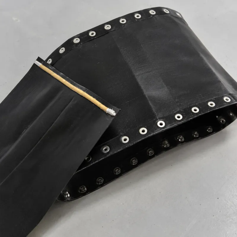
A guide cord needs a matching machine interface. Its projection, attachment and lateral position must clear the return path and the smallest relevant roller. Eyelet rows also need defined hole size, pitch, edge distance and hardware compatibility. Match these features to the drawing rather than copying them from a photograph.
State finished endless circumference separately from open belt length. Record measurement temperature and whether the belt is relaxed or measured under an agreed force. A worn belt can contain permanent distortion, edge damage or a shortened repair; preserve its part reference and compare it with the machine drawing.
05 / Fusing machine belt selection
Treat tracking as a belt-and-machine interaction
A belt that moves sideways needs a recorded pattern before an adjustment. Note the edge position after warm-up, during loaded running and after a stop. Identify whether drift is steady, changes with loading or repeats at one point in the belt revolution.
Inspect roller alignment, deposits on rollers, edge rubbing, guide engagement and the condition of the tracking mechanism under the machine’s maintenance procedure. Use the prescribed tension and adjustment sequence. Increasing tension to suppress drift can add load without correcting the alignment or guide mismatch that started it.
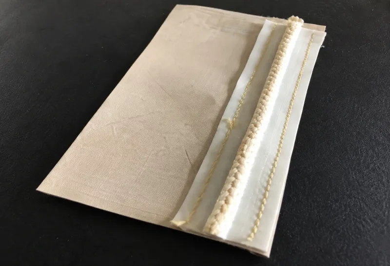
A sewn guide introduces a local attachment and a raised profile. Check the thread, cord and reinforcing strip together, including the return path. Installing a guide on a machine that has no matching interface does not create a complete tracking system.
- Record guide-side position at a repeatable machine datum; include the running state and temperature.
- Check the minimum remaining clearance through a complete revolution.
- Keep left/right orientation and belt running direction on the finished drawing.
- Confirm the selected grade and grounding arrangement when static control forms part of the machine requirement. Black colour alone is insufficient.
06 / Fusing machine belt selection
Calculate residence time, then measure the fusing conditions
For a belt moving at a steady speed, transit time through a defined zone follows its length. With zone length L in metres and belt speed v in metres per minute, transit time in seconds is 60 × L / v. Use the effective zone length along the belt path, not the overall machine length.
The example below assumes a 1.20 m heated zone. Increasing speed from 3 to 6 m/min reduces transit time from 24 to 12 seconds. That calculation establishes time in the zone. The fabric–adhesive interface temperature still depends on heat transfer, the assembly and the machine’s control behaviour.
Measure the fusing exposure using a method suited to the press and garment assembly. Record the controller setting separately from the measured interface result. Verify pressure distribution and the cooling/handling sequence as part of the same trial. Retain the interlining’s approved processing window when evaluating a replacement belt.
CALCULATED EXAMPLE / FIXED 1.20 m ZONE
Double the speed. Half the time in the zone.
Transit time (s) = 60 × zone length (m) ÷ belt speed (m/min)
| Belt speed | Zone transit: 60L / v | One revolution: 60C / v |
|---|---|---|
| 2 m/min | 36 s | 108 s |
| 3 m/min | 24 s | 72 s |
| 4 m/min | 18 s | 54 s |
| 6 m/min | 12 s | 36 s |
07 / Fusing machine belt selection
Use repeat spacing to locate a periodic mark
A local splice feature returns once per belt revolution. Under steady motion, a mark associated with that feature can repeat at an interval corresponding to belt circumference. In the 3.60 m example, at 3 m/min the same joint returns every 72 seconds. At 6 m/min it returns every 36 seconds; the belt distance between returns remains 3.60 m.
Compare the time and position of the mark with an identifiable belt feature, using the machine’s permitted observation method. Check upper and lower belts independently when they have different circumferences. A roller deposit can produce its own periodic pattern, so repeat spacing narrows the investigation rather than proving the cause.
Keep the material feed and any slip in the record. Garment pieces loaded at intervals do not form a continuous distance record. Confirm a suspected cause by comparing panels processed across the identified seam with panels processed away from it.
08 / Fusing machine belt selection
Separate adhesive residue from a damaged release face
Compare the surface before and after the machine-approved cleaning procedure. Removable adhesive sits on the working face. Exposed glass yarns, a permanent crease, cuts and missing coating indicate damage. Cleaning removes compatible residue; it does not rebuild the release layer.
Use cleaning tools and liquids approved for the complete belt, including joint, edge reinforcement, stitching and guides. Avoid abrasive scraping and sharp folds. A cleaner compatible with PTFE resin alone may still affect another part of the fabricated assembly.
Keep a record of where contamination first appears. Check interlining orientation, adhesive transfer, loading and the established fusing conditions before attributing every release problem to the belt grade. Follow the equipment procedure for isolation, cooling, cleaning and restart.
| Observation | Checks that help distinguish causes | Next controlled comparison |
|---|---|---|
| Panels stick or drag | Residue, coating condition, stripping interface and actual fusing exposure. | Clean and inspect; compare the same assembly under the recorded cycle. |
| A line repeats periodically | Splice return, local belt damage, roller deposits and panel timing. | Compare seam-crossing and seam-free positions. |
| The belt drifts to one side | Alignment, guide engagement, deposits, load distribution and warm-up state. | Record edge position through a revolution using the prescribed machine setup. |
| One edge frays or rubs | Contact at that edge, guide position, width and return-path clearance. | Verify fitted geometry before replacing with the same dimensions. |
| Bond is weak or uneven | Interlining, measured exposure, pressure, cooling and contamination. | Evaluate bond quality separately from release appearance. |
| Surface shows weave print | Belt texture, garment face, contact pressure and heat exposure. | Compare surface candidates on the same sensitive fabric. |
09 / Fusing machine belt selection
Run a controlled A–B–A comparison
Use the accepted belt as A and the candidate as B. Run A, then B, then A again where changeover is practical. The final A run checks whether warm-up, material variation or contamination shifted the process during the comparison. Where repeated belt changeover is impractical, use a documented baseline and repeat the reference checks after the candidate run.
Keep fabric and interlining lots, panel orientation, loading, measuring method and cleaning state consistent. Compare at the same verified process conditions. If a candidate needs an adjustment within the approved process window, record it as a separate trial rather than combining it with the direct comparison.
For an initial engineering screen, use three lateral positions—left, centre and right—and two longitudinal positions—across the splice and away from it. Three repeats at each position give 18 observations per belt condition. This is a proposed screening layout, not a statistical qualification or a completed experiment. Set the final sample size from the garment requirement and production variability.
| Stage | Record | Acceptance basis |
|---|---|---|
| Incoming belt | Sample ID; body/joint thickness; overall/working width; circumference; guides. | Approved part drawing and retained surface reference. |
| Installed running | Warm-up state; lateral position; minimum clearance; guide and joint passage. | Machine setup and available clearance. |
| Fused panel | Release; weave/gloss change; residue; marks; measured exposure and pressure check. | Agreed garment appearance and fusing process. |
| Bond after conditioning | Test method; specimen width; peel conditions; force; separation mode. | Garment/interlining specification and agreed laboratory method. |
| After required care | Specified laundering or dry-cleaning cycle; bond and appearance after conditioning. | The garment care and durability requirement. |
| Repeat duty | Cycle count, cleaning intervals, edge/joint condition and change from baseline. | Agreed service trial; a short screen does not establish belt life. |
10 / Fusing machine belt selection
Approve bond quality separately from clean release
A panel that leaves the belt easily has passed a release observation. Bond approval needs its own method, conditioning and acceptance limit. Test the fused assembly after the required conditioning and, where specified, after the garment care cycle. Record adhesive separation, fabric rupture or another observed failure mode alongside the force result.
For a force comparison, retain specimen width, peel geometry and test speed with the result. A force of 12 N measured on a 25 mm wide specimen corresponds to 0.48 N/mm. This unit calculation does not establish an acceptable bond, and normalising by width does not make results from different test methods interchangeable.
Keep spatial results visible. A low edge result can disappear inside an overall mean. Compare individual left, centre and right readings with the requirement and investigate their spread before accepting the average.
| Decision | Evidence needed | Release decision |
|---|---|---|
| Machine fit | Dimensions, tracking, clearances, connection and guide passage. | Accept the fabricated belt geometry. |
| Garment quality | Face appearance, release and bond results under the required cycle. | Accept the belt/process combination for that assembly. |
| Service suitability | Documented running duty, cleaning and condition over the agreed trial. | Accept the inspection and replacement plan for that duty. |
11 / Fusing machine belt selection
Order the approved construction as a repeatable part
Build the order around the approved drawing and retained sample. Include machine model and belt position, finished dimensions and measurement state, surface reference, splice drawing and full profile, guide/eyelet details, running direction and operating duty.
Record the approved garment trial separately from the belt’s material specification. A successful trial on one interlining and face fabric does not approve every adhesive or garment. Keep a revision number with any change to coating grade, surface finish, splice or guide construction so the next replacement can be checked against the same reference.
Buyer questions
Fusing belt selection questions
What is a PTFE fusing machine belt made from?
The construction discussed here is woven fiberglass fabric coated with PTFE and fabricated into a machine-specific belt. The coating supplies the release face; the reinforcement, splice, edges and guides define the complete running part.
Does a smoother belt prevent all fabric marking?
A smoother contact face can reduce the prominence of weave texture. Final appearance also depends on the fabric, interlining, pressure and heat exposure. Approve it with cooled production-fabric panels and a retained appearance reference.
Is a seamless belt always required?
The machine and garment requirement determine the permitted construction. A spliced belt needs an approved full joint profile and a seam-crossing trial. Confirm a claimed seamless construction separately; endless simply means a closed loop.
Why does a new fusing belt run to one side?
Check roller alignment, deposits, guide engagement, fitted dimensions and the tracking mechanism. Record whether drift changes with warm-up, load or belt position. Use the machine’s specified tension and adjustment procedure.
Can the upper and lower belts use the same specification?
Specify each position against the machine drawing. Circumference, surface, guide arrangement, running direction and contact duty may differ. Similar colour and thickness do not establish interchangeability.
Is a black PTFE belt anti-static?
Black colour does not establish an anti-static grade. Identify the material, resistance test method and conditions, and confirm the belt’s contact and grounding arrangement for the machine requirement.
How do I compare two fusing belts fairly?
Use the same fabric and interlining lots, loading, cleaning state and verified process conditions. Compare fit, release, appearance and bond quality separately. Keep seam-crossing and seam-free observations, then evaluate the required care and running duty.
Your next step
Discuss a fusing belt replacement
Send the machine model, upper or lower belt position, dimensioned drawing, photographs of both faces and the garment or running problem to resolve. Include the approved surface sample and trial requirements when available.
Discuss a fusing belt replacement