Quick answer
Choose a PTFE mesh conveyor belt around the smallest part, its contact surface and the installed support. Then specify the belt width, finished circumference, joint, edges and guides against the machine drawing. Check actual belt temperature separately from UV irradiance and dose at the part. Approve the replacement with a loaded running trial and the production process’s cure acceptance criteria.
01 / UV curing belt selection
Define the belt’s job before choosing a mesh
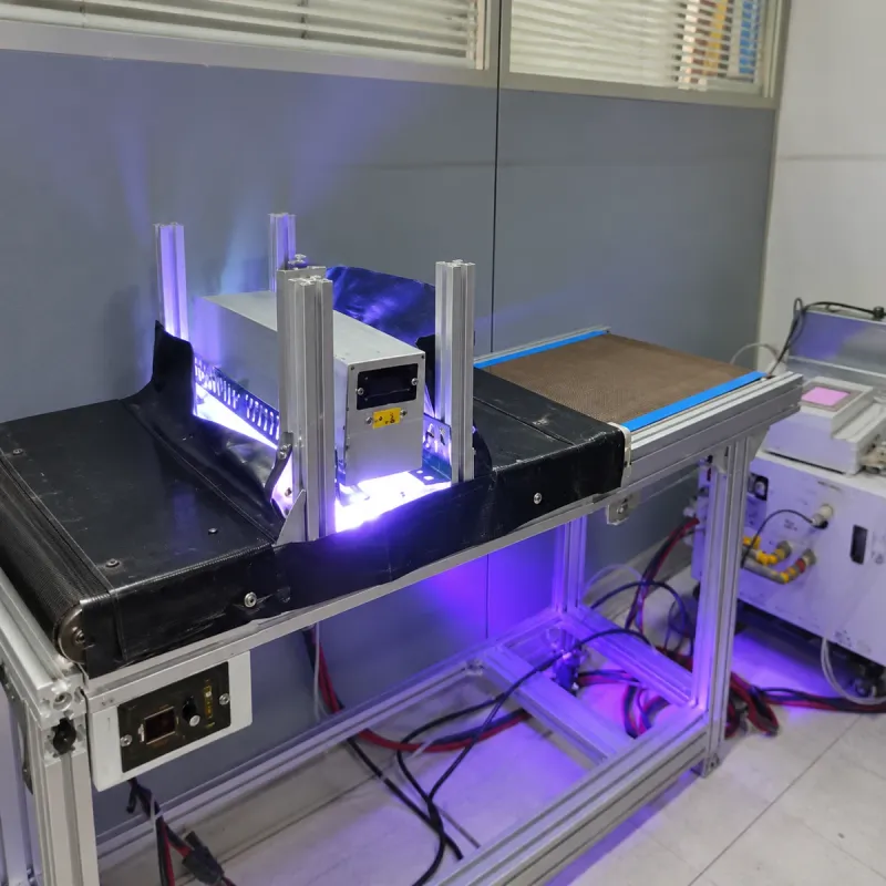
A UV curing belt carries coated, printed or bonded parts through an exposure zone. It must hold them in a repeatable position while passing over rollers, supports and return-path hardware. PTFE-coated fiberglass open mesh combines a release surface with openings between the coated yarns. Those openings provide a route for ventilation where the machine and load leave that route clear.
UV curing and thermal drying are different processes. UV curing uses light matched to the ink, coating or adhesive. Hot-air and infrared dryers rely on a thermal process. A line can combine these functions, but a belt selected for heat resistance has not, by that fact alone, established the conditions needed to cure the product.
Begin with the part and the machine: what is being conveyed, which face touches the belt, where the coating remains wet, and whether the part sits directly on the mesh or in a fixture. A replacement must preserve the working arrangement that produced an acceptable part.
| Check | Establish | Accept against |
|---|---|---|
| Part and cure | Part height, contact face, lamp arrangement, line speed and measured exposure at the curing surface. | The established ink, coating or adhesive cure criteria. |
| Belt and heat | Actual belt temperature, exposure duration, return-path cooling and all joint and edge materials. | The finished belt construction’s approved operating limits. |
| Machine fit | Width, circumference, rollers, support, tracking, clearances and installation access. | The machine drawing and loaded running trial. |
02 / UV curing belt selection
Select the opening around the smallest contact footprint
Overall part length is a poor measure of support. A large component can rest on narrow feet; a thin sheet can curl; a soft coating can press into the weave. Record the smallest feature touching the belt and how the part behaves during loading, acceleration and unloading. Include loose fragments or components that must stay on the conveyor.
Specify clear aperture in both directions on the finished coated mesh. Record pitch, overall thickness and the condition in which the sample was measured. The coating occupies space around the yarns, so an uncoated weave description does not define the finished opening.
Geometric open area is the fraction of projected mesh area occupied by openings. It describes geometry, not measured air permeability, load capacity or UV transmission. Evaluate the belt together with the support bed, fixture and loaded coverage. A closed support plate blocks through-flow even beneath an open mesh.
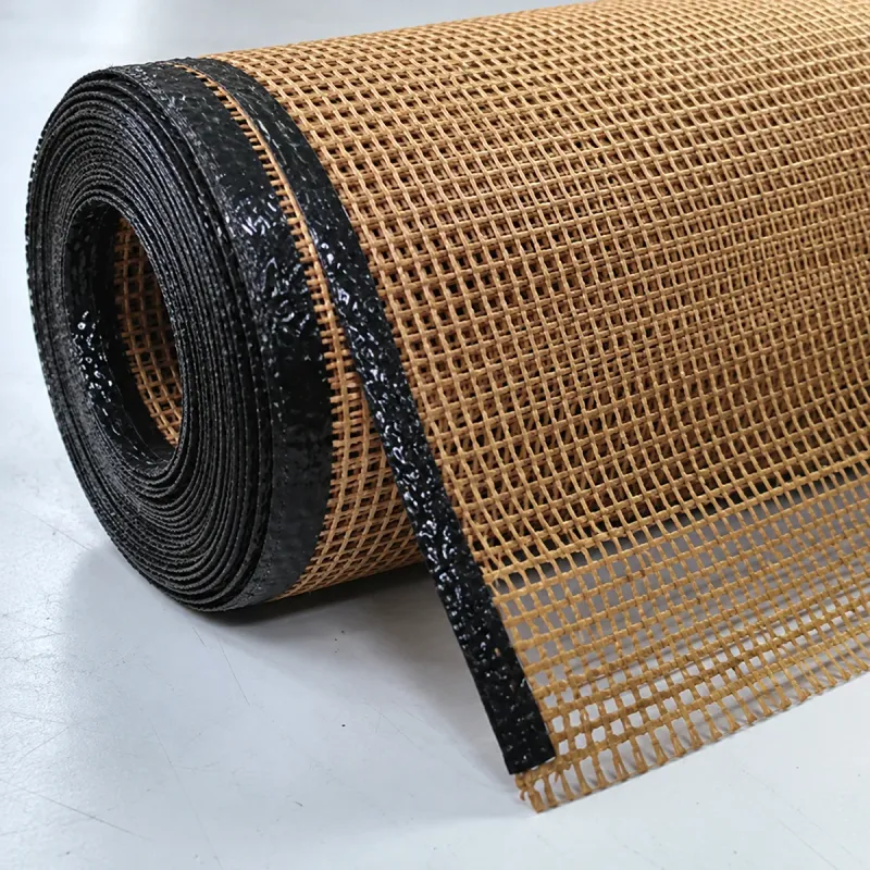
- Narrow feet and small parts: check support through the full belt revolution, including the connection.
- Flexible sheets: inspect sag, curl, flutter and movement over support transitions.
- Wet or contact-sensitive surfaces: assess release and the acceptable underside weave imprint.
- Fixtures and pallets: include their mass, footprint and effect on ventilation and light access.
03 / UV curing belt selection
Separate overall belt width from the usable process lane
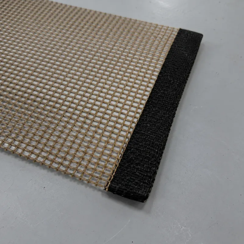
Overall width includes edge reinforcement. The process lane is the area available to carry parts within the machine’s permitted loading and illuminated width. Guides, edge bands and support clearances take up space. A nominally wider belt does not automatically provide a wider curing lane.
Record both edge-band widths, guide positions and their distance from the belt edge. Check the upper and lower profiles against rollers and the return path. At the transverse connection, inspect the local surface height and openings: reinforcement or an overlap changes that region even when the parent mesh stays unchanged.
| Dimension | Drawing detail |
|---|---|
| Overall width | Finished width and tolerance, including edge treatment. |
| Usable carrying lane | Permitted loading width, edge clearance and relationship to the illuminated area. |
| Edges and guides | Band widths, thickness, guide cross-section and position on each face. |
| Connection region | Finished thickness on both sides, connector projection and local opening pattern. |
| Finished circumference | Closed-loop length and the agreed measurement condition; distinguish it from an open blank length. |
04 / UV curing belt selection
Use line speed to understand exposure time
For a part moving at constant speed through a defined exposure length, time equals length divided by speed. Use consistent units and measure the exposure length along the direction of travel. The enclosure length or lamp housing width is not necessarily the effective exposure length.
For example, a 0.30 m exposure length at 6 m/min gives 0.05 minutes, or 3 seconds. Doubling the speed halves that time. This calculation describes motion through an assumed zone; it does not determine the dose delivered to the part or establish a curing recipe.
Exposure time = length ÷ speed
0.30 m ÷ 6 m/min = 0.05 min = 3 seconds
Illustrative motion calculation. Actual UV dose requires measurement along the part’s exposure path.
05 / UV curing belt selection
Measure UV at the curing surface, not just at the belt
Irradiance is incident UV power per unit area, commonly expressed in mW/cm² or W/cm². Dose, also called energy density, is irradiance accumulated over the exposure time and is expressed in mJ/cm² or J/cm². Specify the measurement band with the reading: a result without its spectral range is incomplete.
At constant irradiance, dose equals irradiance multiplied by time. Across a conveyor, the light level changes as the part enters, passes under and leaves the source. Use a suitable radiometer to capture the exposure at the relevant height and travel path. Record its identity, calibration status, spectral response and orientation so later readings remain comparable.
Part height, fixtures and lamp arrangement determine the light that reaches the curing surface. A reading taken on an empty belt is a different measurement from one at a raised bond line. Map relevant positions across the working width, and repeat the check after changing belt thickness, support height or part presentation.
- Keep the light source and measurement instrument appropriate to the process wavelength range.
- Record lamp-to-curing-surface distance, line speed and measurement position together.
- Evaluate shadows from parts, fixtures and belt structures where the optical path passes through them.
- Verify the finished product with the specified cure test; a dry-looking or tack-free surface alone is not a universal acceptance criterion.
06 / UV curing belt selection
Check the complete belt against actual heat exposure
Measure belt temperature at the process station and examine repeated operation, warm-up and the machine’s normal hold or interruption states. The lamp setting and the surrounding air temperature do not identify the hottest belt location. Follow the equipment procedure when evaluating these states.
A fabricated belt includes more than the coated mesh. Joint materials, edge reinforcement, guide attachments and stitching each have their own limits. Specify the normal and peak temperatures, exposure duration and repeated bending duty for the complete assembly. Do not substitute a PTFE resin melting point for a belt operating rating.
During a trial, inspect the same marked locations after running and cooling. Record dimensional change, mesh distortion, coating cracks, exposed yarns and changes around the joint or edges. Keep temperature readings with the sample identity and cycle conditions; a visual inspection alone does not establish long-term service life.
07 / UV curing belt selection
Match the joint and tracking details to the conveyor
The belt passes through the exposure zone once per revolution, but its joint also travels around every roller and return-path obstruction. Check the smallest roller, reverse bends, support transitions and available clearance against the complete joint profile. The underside matters as much as the carrying face.
Confirm whether the belt can be installed as a closed loop or must be connected on the machine. Record access for joining and removal, guide engagement and any permitted connector projection. The existing joint guide below compares connection families; the UV application adds the requirement to check how the assembled connection affects part position and the exposure path.
Match guides to the equipment rather than using them to compensate for an unresolved alignment problem. During the trial, record tracking empty and loaded, cold and at operating condition. Follow the machine’s tensioning procedure and retain the agreed adjustment position with the belt specification.
08 / UV curing belt selection
Specify static control separately from colour
Black PTFE mesh is not automatically anti-static. Where static control is required, specify the finished belt’s electrical requirement, test method and measurement conditions. Include the connection, edges and the conveyor’s grounding arrangement in the review.
An anti-static material designation describes a particular construction; it does not qualify the entire conveyor or every electronics application. Request the relevant finished-material data and agree how the installed assembly will be accepted. Neither a dark coating nor an application photograph replaces that information.
09 / UV curing belt selection
Approve the replacement with a controlled running trial
Assign the candidate a sample identifier and record its mesh, joint, edges and guides before installation. Compare it with the approved production setup using the same parts, loading pattern, fixture and process conditions. If the replacement changes several features at once, record each change rather than attributing the result to aperture alone.
Agree the product acceptance criteria before the run. Depending on the application, these include the specified adhesion, hardness or other cure-related property, together with permitted marking and handling damage. Keep the product check separate from belt fit, tracking and condition checks. A belt can run correctly while the product receives an unacceptable exposure.
| Stage | Record | Acceptance question |
|---|---|---|
| Before fitting | Sample ID, finished dimensions, aperture, joint profile, edges and guide position. | Does the belt match the drawing and installation method? |
| Initial running | Machine adjustment, tracking, roller passage, return clearance and connection passage. | Does the full assembly run without interference? |
| Loaded exposure | Part layout and height, speed, lamp distance, relevant UV readings and belt temperature. | Are the parts supported within the established process conditions? |
| Product inspection | Specified cure result, contact marks, movement, release and handling condition. | Does the product meet its agreed quality requirements? |
| After cooling and cleaning | Cooled dimensions, residue, coating, yarns, edges and connection condition. | Does the belt retain the required condition after the cycle? |
| Repeated running | Run duration, cycles, settings and changes at identified inspection points. | Is there sufficient evidence for the intended production duty? |
10 / UV curing belt selection
Use the fault pattern to choose the next check
Mark where a problem occurs across the width and whether it repeats at a fixed position on the belt. Record its timing against a full revolution. This distinguishes an area worth inspecting on the belt from a station or loading condition worth investigating on the machine; the pattern guides the inspection rather than proving a single cause.
| Observation | Inspect first | Then compare |
|---|---|---|
| Part tilts or drops at the same belt position | Local openings, damaged yarns, connection height and support beneath that position. | The smallest contact footprint and the allowed connection profile. |
| Cure differs across the working width | UV measurements at part height, lamp condition, shadows and loading positions. | The qualified exposure window and each part’s cure result. |
| A mark repeats once per revolution | The matching belt location for residue, a raised connection or damaged coating. | Product contact orientation and acceptable surface finish. |
| One edge wears faster | Machine alignment, guide contact, roller buildup and loaded tracking. | Edge construction, clearances and the prescribed tensioning procedure. |
| Release becomes difficult | Ink, adhesive or coating residue and the condition of the release face. | The approved cleaning method and post-cleaning sample condition. |
11 / UV curing belt selection
Prepare the belt drawing and operating brief
SIFMAT supplies PTFE-coated fiberglass open mesh in roll, cut-part and fabricated-belt formats. For a UV curing replacement, send the machine reference and a dimensioned belt drawing together with the working conditions. Include photographs of the existing belt on both faces, the connection, guides and installation path.
Measure the machine as well as the old belt. Wear, damage and the current adjustment position affect a used sample’s dimensions. State how circumference was measured, identify the guide reference edge and separate overall width from the usable carrying lane.
- Part: material, smallest contact footprint, mass, wet contact areas and any fixture.
- Belt: width, finished circumference, aperture, thickness, joint, edge widths and guide drawing.
- Machine: smallest roller, support arrangement, installation access and tracking method.
- Process: UV source type and wavelength range, part height, line speed, actual temperature and exposure conditions.
- Acceptance: product cure criteria, allowed contact marks, static-control needs, cleaning method and sample-trial requirements.
Buyer questions
UV curing conveyor belt questions
Why is PTFE-coated fiberglass mesh used in UV curing conveyors?
It provides a release surface on a reinforced open weave. The openings support ventilation where the load and machine leave a through-path, while the finished belt carries the parts through the exposure zone. Selection still depends on part support, temperature, machine geometry and the complete belt construction.
Does a larger mesh opening improve UV curing?
A larger opening changes support and the unobstructed area; it does not establish the dose reaching the curing surface. Judge the opening against the part footprint and actual light path, then measure exposure and verify the product’s cure result.
Does a PTFE mesh belt transmit UV light?
The openings leave clear paths through the weave, but geometric open area is not a UV transmission rating. Coated yarns, supports, fixtures and parts affect those paths. If light must reach a surface through the belt, measure that exposure in the installed arrangement.
Can the same belt be used with UV lamps and UV LED systems?
UV lamps and UV LED systems have different spectral and thermal conditions. Review the complete belt against the actual machine, part support and measured heat exposure. Confirm the light source and process measurements for the material being cured before approving a replacement.
What temperature rating should I specify?
Specify normal and peak belt temperature, duration and operating states, then confirm the complete assembly’s limit. The mesh, connection, edge reinforcement and guides must all suit that duty. A base-material rating does not by itself rate the finished belt.
Is black PTFE mesh anti-static?
Colour does not establish anti-static performance. Request the specified construction’s electrical data, measurement method and conditions. Where static control is required, review the belt connection and installed grounding path as well as the parent mesh.
What should be checked after replacing a UV curing belt?
Check full-revolution tracking, joint passage, support, part height and actual heat exposure. Recheck the relevant UV readings and the product’s cure result under the established production conditions. Record the replacement specification and acceptance results for the next order.
Your next step
Discuss Your UV Curing Belt
Send the machine reference, belt drawing and process conditions. Include the part footprint, existing joint and edge details, actual belt temperature and the issue you need the replacement to resolve.
Discuss Your UV Curing Belt